 |
| Home |
|---|
| Who are we? |
| Event calendar |
| Sections in the Club |
| O-gauge |
| On30 Scale |
| OO-gauge |
| HO Scale |
| TT:120 Scale |
| N Scale Modular |
| Z Scale |
| Lego Railway |
| Contact us |
| NMRA |
| Useful Links |
| Photo Galleries |
| Banners |
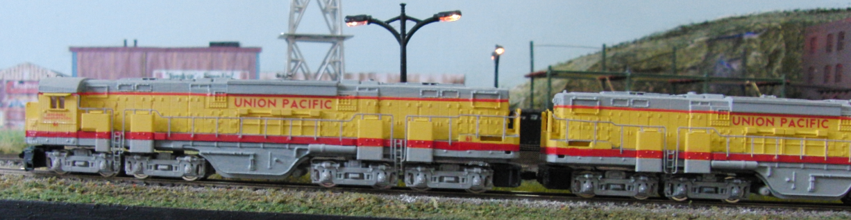
N Scale Modular DCC
Track power and train control
The trains on the layout are powered and controlled using Digitrax DCC equipment. We have two "suitcases" that contain the main DCC components. The main "big" suitcase contains:
- The command station, a DCS100. The booster portion of this device is used to power part of the scenic portion of the layout through some
- PSX circuit breakers.
- There is also a DB150 booster that powers the yard at that end of the layout.
- An LNRP which splits the LocoNet communications network into a "core" network (using white cables) connecting the command station, boosters etc. and a "peripheral" network (using black cables) which joins non-core components (stationary decoders, computer interfaces etc.).
- A UR92DCE which provides Digitrax "Duplex" radio facilities for radio throttles (a mix of DT402DCE and UT4DCE devices).
- All the power supplies for these components are brought together to a single "kettle lead" plugged into the suitcase which is plugged into the mains via an RCD device.
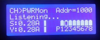
- Another device in the suitcase is an Arduino which monitors the PSX circuit breakers and Hall-effect current sensors which provide remote monitoring of the output of the boosters/PSXs to the LocoNet via a GCA185 LocoNet shield and also to a local LCD display.
The second "small" suitcase contains essentially the same equipment with the exception of a second DB150 in place of the DCS100.
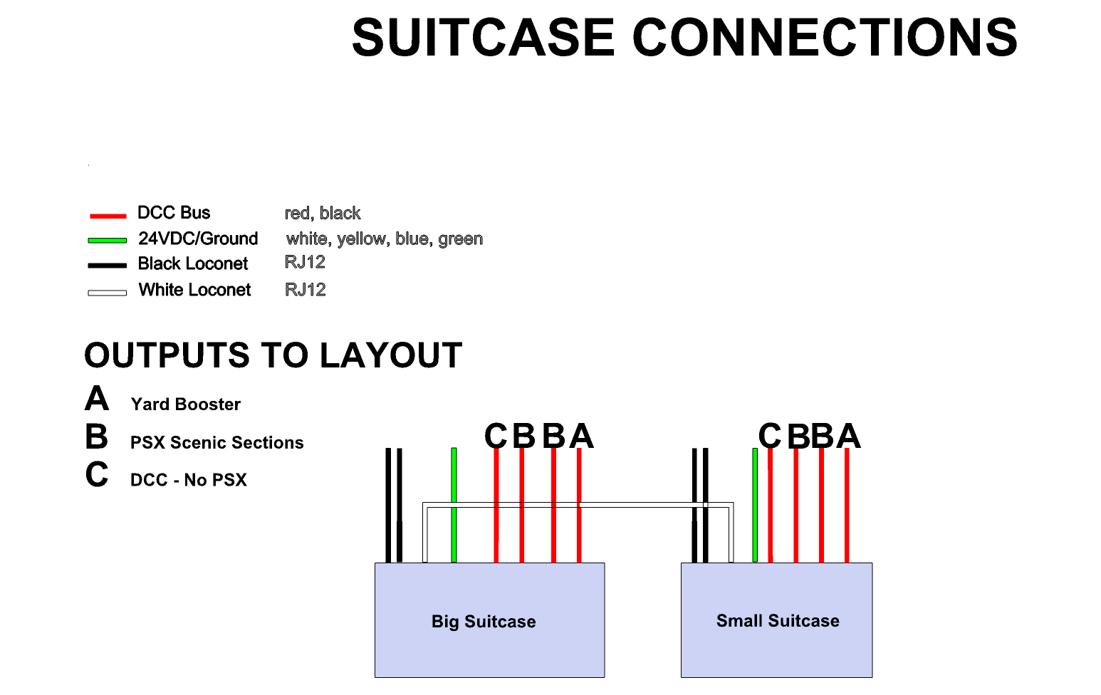
The suitcases have the connections and are connected as shown above.
A set of procedures for the designated "electrical engineer" for the day (PDF, 35Kb) have been assembled to ensure that the layout is powered up and down in a consistent and functional order and a set of procedures for the designated "mechanical engineer" (PDF, 21Kb) for making/breaking all the mechanical connections are under development. All these devices are PAT tested regularly.
Turnout and route control
All turnouts on the layout are currently controlled by SEEP point motors. Those in the yards and Solent Summit station are controlled using Sig-naTrak (ex-CML) DAC20 stationary decoders.
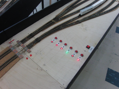
The DAC20 for Solent Summit is in a detachable control panel and driven by momentary contact push-buttons used to select routes into one half of each of the station tracks. The point motors operating the turnouts that make up the routes are driven using Digitrax DS64s. A Sig-naTrak DTX8A daughter board is used to illuminate LEDs indicating the position of turnouts, and thus the route selected.
Each of the storage yards is normally fed by two turnout fan modules each of which is controlled by a DAC20.
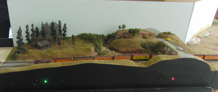
Also mounted under these modules is an Arduino with a GCA185 LocoNet shield. These Arduinos are set up as stationary decoders that listen on LocoNet for switch commands included in the DAC20 routes which instruct the Arduino to turn the red/green LED for the selected track to green indicating which yard track is lined for use.
Also attached to the DAC20 on the in-bound side of the yard in a DPDT relay which switches the polarity of all the yard tracks to match the main line depending on whether an in-bound or out-bound route has been selected. (We have tried various auto-reversing devices including that built into the DB150 without success; we believe that the sheer length of the yards and number of sound locomotives and lit coaches in the yard prevented the AR from tripping reliably.)
Turnouts on other modules are controlled by momentary contact switches driving the point motor via a CDU.
Monitoring
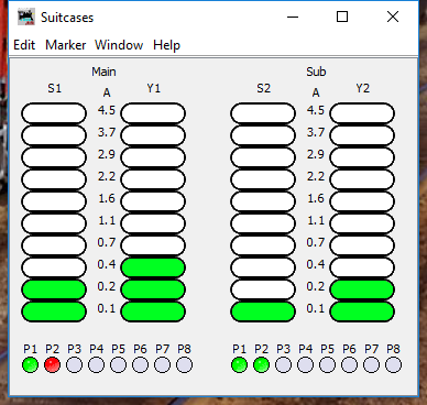
Routinely we have a PC running JMRI PanelPro under Linux monitoring the LocoNet via a PR3. JMRI is used to monitor the activity on LocoNet and the DCC "slots" in the command station. A JMRI "panel" is used to display the sensor messages transmitted by the Arduinos in the suitcases to report the power being drawn from the boosters and if the PSX circuit breakers have been triggered by a short circuit.
Sequencing
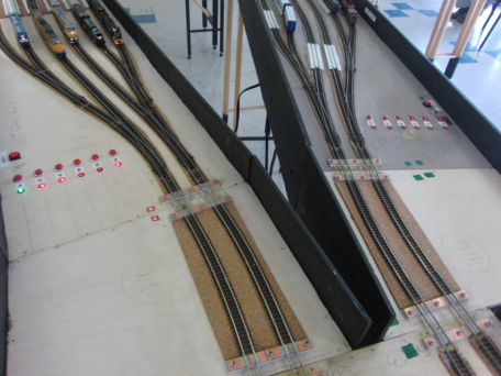
The majority of modules are single track and there are limited passing places (currently 8' at Solent Summit and potentially 13' if either the Dilithium Fuels/Cascade Falls pair or Bob's Pickle Factory/Cement work are in use). We regularly run trains of 20' to 24' (the maximum the yards currently allow) and so train movements needs to be carefully orchestrated to ensure that we do not "deadlock" with two trains that cannot pass each other at a passing place or trains meeting head-on on a single track and also that there is the correct space available in the receiving yard. We also desire that there should be something moving all the time somewhere on the layout.
Therefore at shows we normally work to a pre-defined schedule of movements. In addition, with as many as 50 locomotives on the layout we have to ensure that we avoid having more than one with the same decoder address! To ensure this, each member of the team provides the sequence coordinator a list of the trains they would like to run, the locomotive addresses and their length a week or two before the show. These trains are distributed between the yard tracks and a sequence of movements (essentially a timetable "string diagram") constructed and tested (on paper). This can take between 8 and 12 hours to construct and test for a full layout with exchanges of trains into places like the Mine and Power Station.
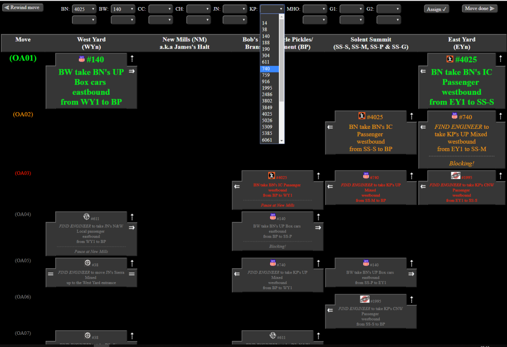
A PC is located near one of the yards which displays (illustrated above) the sequence movement-by-movement and the "dispatcher" cordinates "engineers" to actually drive the trains according to the plan. This PC may also allow the dispatcher to montior the layout with strategically placed web cameras to enable them to see what is going on.
We can normally exchange all the trains between the yards and back again between one and three times in a full day of operation depending on the yard lengths and layout complexity.
© 2013-2026 C Hatt for AMRG. |
Email the Web master |
|